Basic principles of topography

In this guide, we present the basic principles of Surveying, the basic instruments, and the most commonly used operations.
This guide introduces the basic principles of Surveying. The most important classical instruments for surveying are levels and total stations, which are used for fieldwork. This guide answers common questions related to the operation and primary applications of these instruments, such as:
- What are the main features of these instruments?
- What factors should be considered when performing a measurement with a level or a total station?
- What effects do instrumental errors have?
- How can these errors be recognized, determined, and eliminated?
- How can simple surveying measurements be carried out?
The use of levels and total stations is illustrated through a series of practical examples. Additionally, the application programs integrated into modern total stations from Leica Geosystems, which allow for optimal and simple surveying tasks, are described. With the support of this guide and the corresponding user manual, any operator will be able to reliably and efficiently carry out simple surveying measurements.
The Surveying Level
A surveying level basically consists of a rotating telescope placed on a vertical axis, used to establish a horizontal line of sight, allowing height differences to be determined and layouts to be carried out.
Leica Geosystems' levels feature a horizontal circle, which is very useful for laying out right angles, for example, when measuring cross sections. These levels can also be used to determine distances optically with an accuracy of 0.1 to 0.3 meters.
The Total Station
A total station consists of a theodolite with an integrated distance meter, allowing it to measure angles and distances simultaneously. Nowadays, all electronic total stations feature an optical-electronic distance meter (EDM) and an electronic angle reader, allowing the barcodes of the horizontal and vertical circles' scales to be read electronically, with the angle and distance values displayed digitally.
The horizontal distance, height difference, and coordinates are calculated automatically. All measurements and additional information can be recorded. Leica total stations feature an integrated program that simplifies most surveying tasks, making them quick and efficient.
The most important features of these programs are described in the "Application Programs" section. Total stations are used when the position and height of a point, or simply the position of the point, needs to be determined.
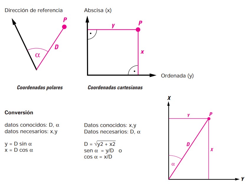
Coordinates
The position of a point is determined using a pair of coordinates. Polar coordinates are determined using a line and an angle, while Cartesian coordinates require two lines in an orthogonal system. The total station measures polar coordinates, which can be converted to Cartesian coordinates within a defined orthogonal system, either by the instrument itself or later in the office.
Angle Measurement
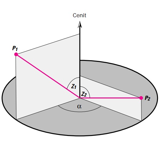
An angle represents the difference between two directions. The horizontal angle α between the directions toward points P1 and P2 is independent of the height difference between the two points, as long as the telescope moves on a strictly vertical plane, regardless of its horizontal orientation. However, this condition is only met under ideal conditions.
The vertical angle (also known as the zenith angle) is the difference between a predetermined direction (knowing the direction of the zenith) and the direction of the point in question. Therefore, the vertical angle will only be correct if the zero reading of the vertical circle exactly matches the zenith direction, which is also only true under ideal conditions.
Deviations are due to errors in the instrument's axes and improper leveling of the instrument (refer to the "Instrumental Errors" section).
Z1 = zenith angle to P1
Z2 = zenith angle to P2
α = horizontal angle between the two directions toward points P1 and P2, that is, the angle between the two vertical planes formed by extending the perpendiculars from P1 and P2, respectively.
Setting up the Surveying Instrument
- Extend the tripod legs as necessary and secure the screws.
- Place the tripod so that the top is as horizontal as possible, firmly securing the legs to the ground.
- Only after this, place the instrument on the tripod and secure it with the central fixing screw.
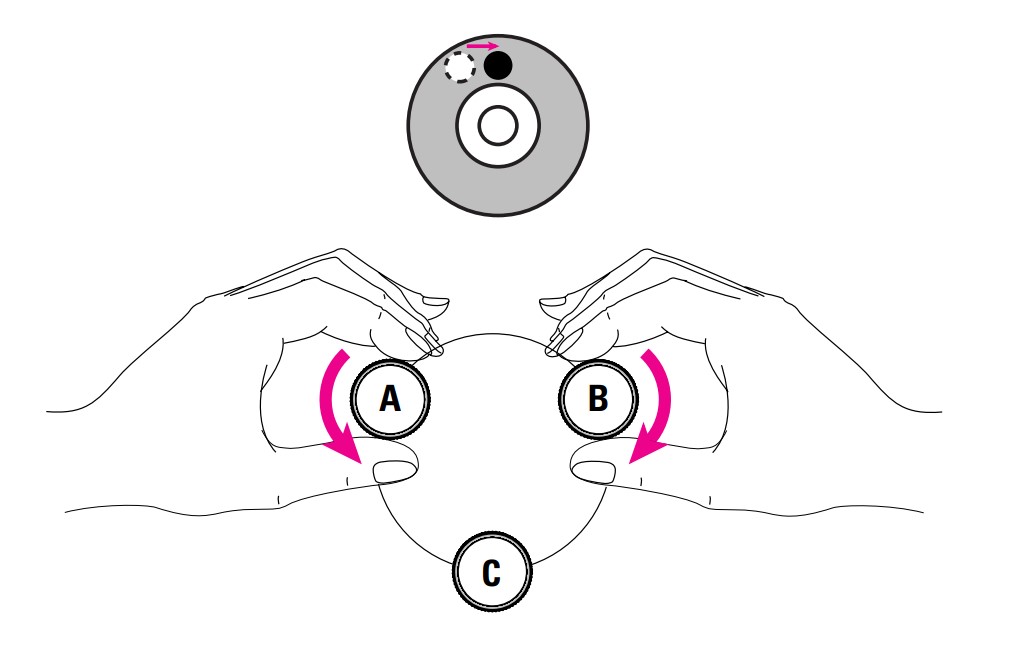
Leveling the Surveying Instrument
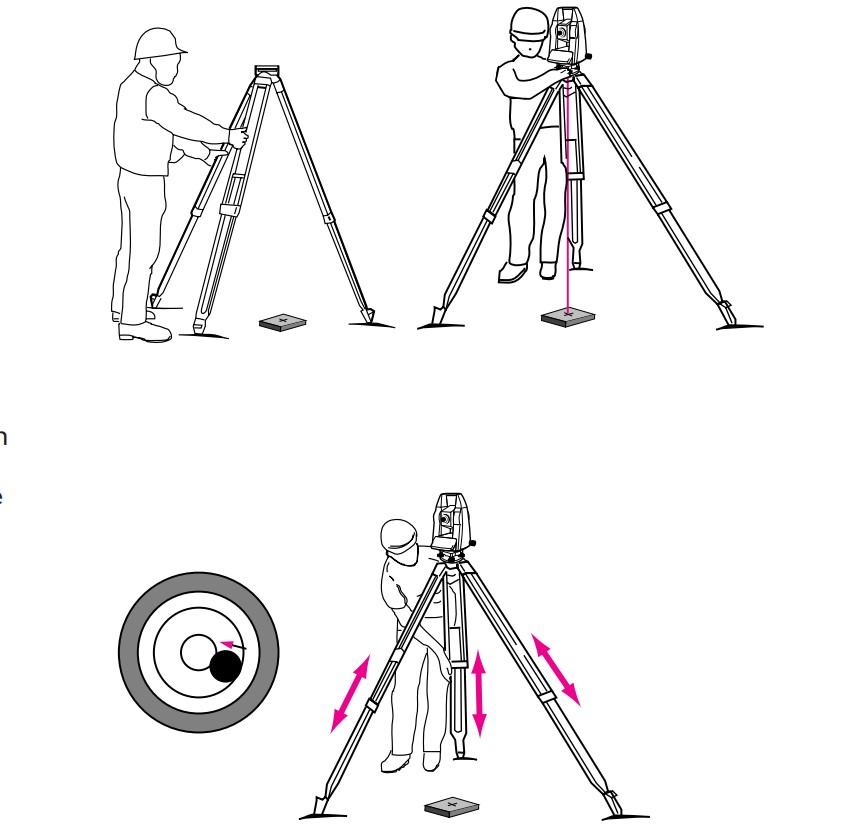
Once the instrument is mounted, level it using the bubble level. Simultaneously turn two screws in opposite directions. Your right-hand index finger indicates the direction in which the bubble should move (top-right illustration).
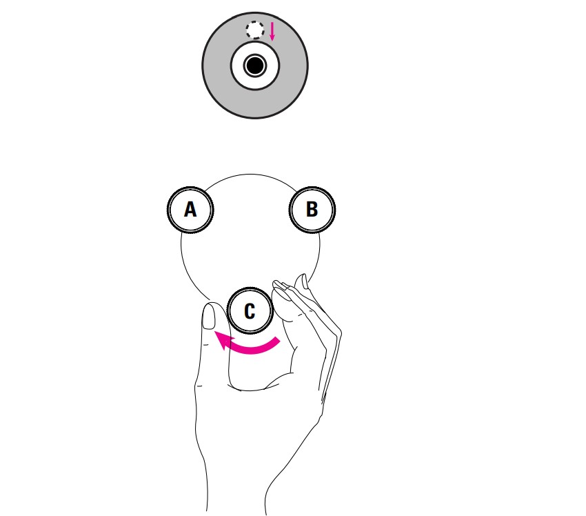
Now, turn the third screw to center the bubble level (bottom-right illustration). To check the leveling, rotate the instrument 180°. After this, the bubble should remain within the circle. If not, further adjustment is required (refer to the user manual). In a level, the compensator automatically performs the final leveling.
The compensator basically consists of a suspended mirror that directs the horizontal light beam to the center of the reticle, even if there is residual tilting in the telescope (bottom illustration). If you lightly tap one of the tripod legs (as long as the bubble level is centered), you'll observe how the line of sight oscillates around the reading and stabilizes at the same point. This is how to check if the compensator can oscillate freely.
Getting Ready to Measure
How to Set Up a Total Station
- Place the tripod approximately over the point on the ground.
- Check the tripod from various sides and adjust its position so that the plate is roughly horizontal and over the point on the ground (top-left illustration).
- Firmly embed the tripod legs into the ground and secure the instrument to the tripod with the central fixing screw.
- Turn on the laser plummet (if using older instruments, look through the optical plummet viewfinder) and adjust the tripod legs until the laser point or optical plummet is centered over the point on the ground (top-right illustration).
- Center the bubble level by adjusting the height of the tripod legs (bottom illustration).
- Once the instrument is leveled, release the central fixing screw and slide the instrument on the tripod plate until the laser point is centered exactly over the point on the ground.
- Finally, retighten the central fixing screw.
Height Difference Between Two Points
The basic principle of leveling is to determine the height difference between two points. To eliminate systematic errors caused by atmospheric conditions or residual errors in the line of sight, the instrument should be placed equidistant from the two points.
The height difference is calculated from the difference between the two series of readings toward points A and B, respectively.
Measurements with the Surveying Level
Optical Distance Measurements with the Surveying Level
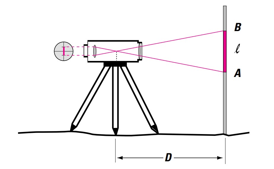
The reticle has an upper and lower line symmetrically positioned relative to the central line (crosshair). The space between them is such that the distance to a point can be calculated by multiplying the corresponding reading by 100.
(The diagram is a schematic representation). Distance measurement accuracy: 10 – 30 cm.
Example: Upper reading on the leveling rod (upper line)
B = 1.829. Lower reading on the leveling rod (lower line)
A = 1.603. Reading of the leveling rod: I = B - A = 0.226
Distance = 100 x I = 22.6 m
Leveling a Line
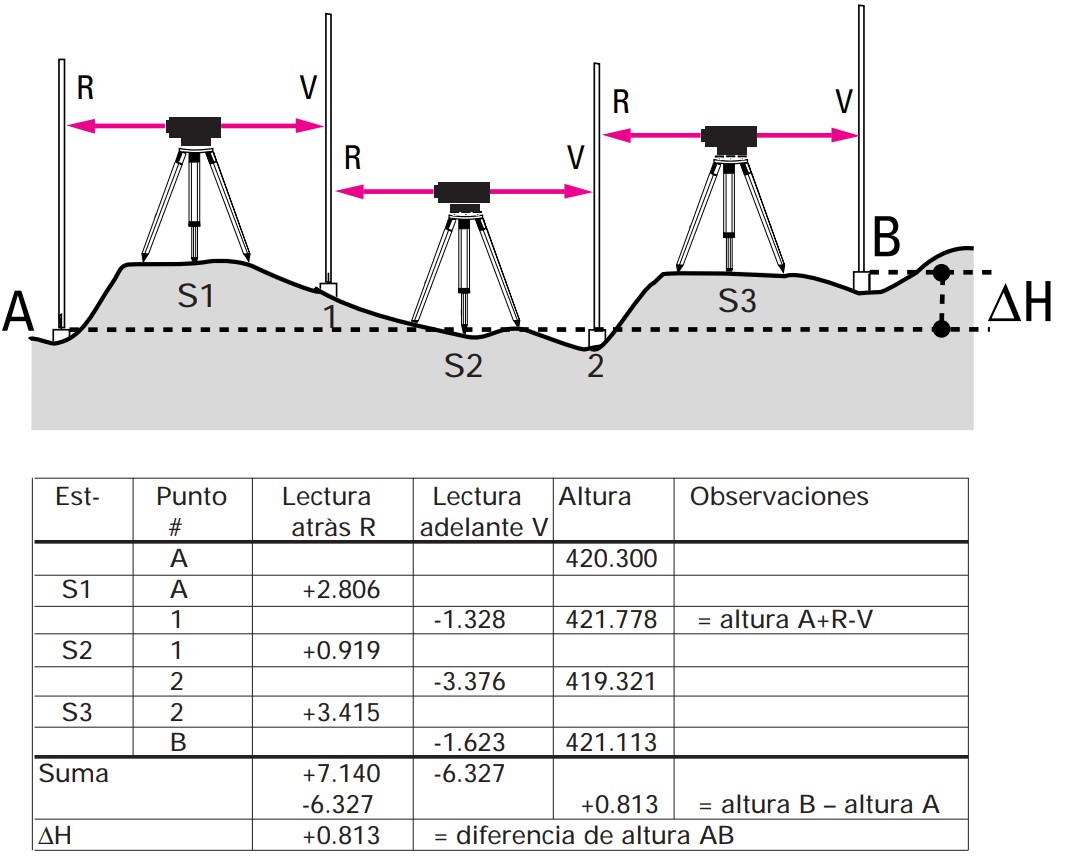
If the distance between points A and B is considerable, the height difference between them is determined by leveling sections of 30 to 50 meters. Calculate the distance between the instrument and the two rods: it should be the same.
- Place the instrument at point S1.
- Place the leveling rod vertically at point A, take the height reading, and record it (back sight reading R).
- Rotate the instrument and place the rod at point 1 on a mark on the ground. Take the height reading and record it (forward sight reading V).
- Move the instrument to point S2 (the rod should remain at point 1).
- Carefully rotate the rod at point 1 so it faces the instrument.
- Take the reading from the rod and continue the same procedure. The height difference between points A and B equals the sum of the back sight reading and the forward sight reading.
Setting Out Heights of Points
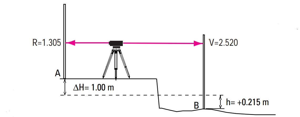
Suppose that in an excavation, point B needs to be set out at a height ΔH = 1.00 meter below the street level (Point A).
- Place the level approximately equidistant between A and B.
- Place the leveling rod at point A and take the back sight reading R = 1.305.
- Place the rod at point B and take the forward sight reading V = 2.520. The required height difference h for B is calculated as: h = V - R - ΔH = 2.520 - 1.305 - 1.00 = +0.215 m
- Drive a stake at B and mark the required height (0.215 meters above the ground level).
With another commonly used method, the reading of the rod is calculated in advance:
V = R - ΔH = 1.305 - (-1.000) = 2.305
Move the rod up or down until the level reads the required value.
Longitudinal and Transverse Profiles
Longitudinal and transverse profiles serve as the starting point for detailed planning and the layout of communication routes (roads) as well as for calculating fill quantities and determining optimal routes relative to the topography. As a first step, the longitudinal axis (road axis) is set out and marked; this involves establishing and monumenting points at regular intervals.
In this way, a longitudinal profile is generated along the road axis by determining the heights of the station points through leveling. The transverse profiles (at right angles to the road axis) are measured at the station points and at terrain elevations. The heights of the points that form the profile are determined using the known instrument height.
First, place the leveling rod on a known station point. The instrument height is the sum of the reading on the rod and the known station point height. Then, subtract the readings of the rod (at the transverse profile points) from the instrument height to obtain the heights of the points in question. The distances from the station point to the various points of the transverse profiles are determined either with a tape or optically using the level.

When graphically representing a longitudinal profile, the heights of the station points are shown at a much larger scale (for example, 10x) than the horizontal scale, which is related to a reference height in whole numbers (top illustration).
Digital Level
The digital levels from Leica Geosystems were the first in the world to be equipped with an electronic digital image processor for determining heights and distances. The barcode on the leveling rod is read electronically and automatically (see illustration). For example, if a construction project requires calculating or controlling several points at different heights, the use of a rotating laser is recommended.
In this type of instrument, the rotating laser beam sweeps across a horizontal plane, which serves as a reference for calculating or controlling heights such as those of established marks. A detector is placed on the leveling rod, which is slid until the laser beam strikes it; the height can then be read directly from the rod. It is therefore unnecessary for the operator to be positioned next to the instrument.
The readings on the rod and the distance are displayed digitally and can also be recorded. Heights on the rod are calculated continuously, eliminating the possibility of errors in reading, recording, or calculation.
Leica Geosystems also offers programs for post-processing recorded data. It is recommended to use a digital level in cases where a considerable amount of leveling is required, saving up to 50% of time.
Rotating Laser
For example, if a construction project requires calculating or controlling several points at different heights, the use of a rotating laser is recommended. In this type of instrument, the rotating laser beam sweeps across a horizontal plane, which serves as a reference for calculating or controlling heights such as those of established marks.
A detector is placed on the leveling rod, which is slid until the laser beam strikes it; the height can then be read directly from the rod. It is therefore unnecessary for the operator to be positioned next to the instrument.
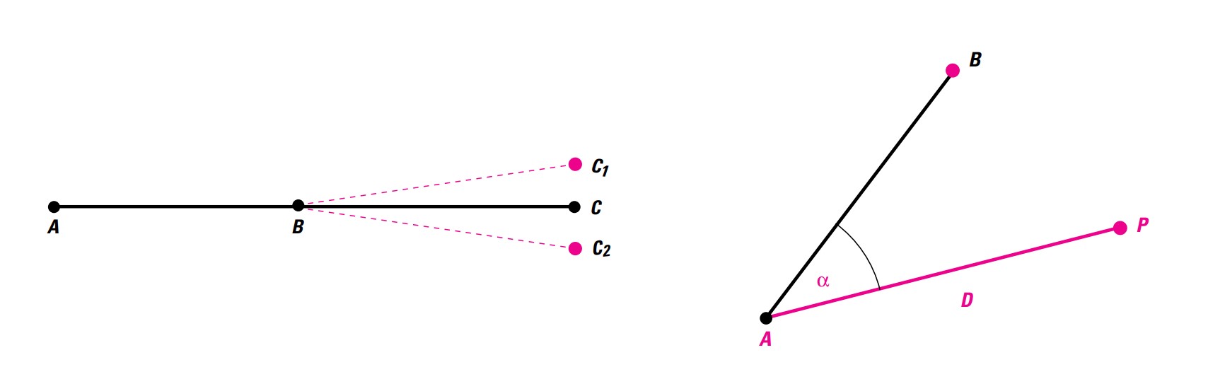
Extrapolation of a Straight Line
- Place the instrument at point B.
- Point the telescope at point A and rotate it toward point C1.
- Rotate the instrument 200 gon (180°) and point the telescope back at point A.
- Rotate the telescope again and measure point C2. The midpoint between C1 and C2 corresponds exactly to the extrapolation of line AB.
The difference between C1 and C2 will be due to an error in the line of sight. When the line of sight is tilted, the influence of the error is a combination of sighting error, axis tilt error, and vertical axis error.
Polar Setting Out of a Point
In this case, the elements to be set out (angle and distance) are in relation to the known point A and a known initial direction from A to B.
- Place the instrument at point A and point it at point B.
- Set the horizontal circle to zero (refer to the user manual).
- Rotate the instrument until the required angle α appears on the display.
- Guide the reflector carrier along the line of sight of the telescope, continuously measuring the horizontal distance until reaching point P.
How to Use the Total Station
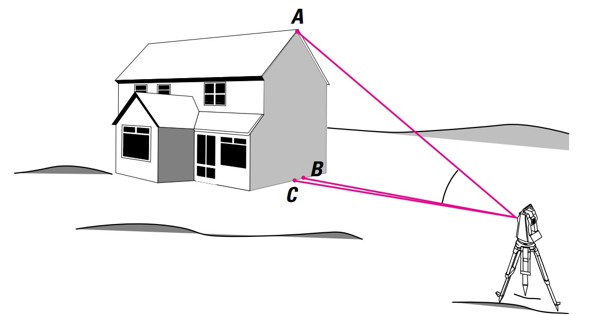
How to Perform Vertical Plumb Line Checks
Plumbing from a height or over a point on the ground, as well as checking the vertical alignment of a structure, can be done accurately using only one face of the telescope, provided it describes a perfectly vertical plane when rotated. To achieve this, follow the steps below:
- Point the telescope at the elevated point A, then aim it downward and mark point B on the ground.
- Rotate the telescope and repeat the procedure from the second position. Mark point C. The midpoint between points B and C will be the exact point for plumbing.
The reason these two points do not coincide may be due to an axis tilt error and/or a vertical axis inclination error. For tasks like this, ensure that the total station is well-leveled to reduce the influence of vertical axis tilt errors.
How to Perform a Survey
To map out a construction site, the position and height of a point on the site are determined by measuring angles and distances. To do this, place the instrument on a point referenced to a local coordinate system. For orientation, choose a second point that is easy to distinguish, and point the telescope at it with the horizontal circle set to zero (refer to the user manual).
If a coordinate system already exists, place the instrument on a known point and align the horizontal circle with a second known point (refer to the user manual).
Measuring Distances Without a Reflector
All Leica Geosystems TCR total stations include both a conventional infrared distance meter for measuring with prisms and a laser distance meter that does not require a reflector. The operator can switch between the two.
This feature is particularly advantageous when the points to be measured are not entirely accessible, such as when measuring boundaries, installing ducts, or surveying along ravines or fences. The visible red laser point is very helpful for marking points during profile measurement in tunnels or interior work.
The handheld "DISTO" distance meter from Leica Geosystems is another simple instrument that uses a visible laser beam and does not require a reflector, making it particularly useful for indoor measurements of distances, areas, and volumes.
Automatic Target Recognition
Leica Geosystems' TCA total stations are equipped with an automatic target recognition (ATR) system. This allows targets to be recognized quickly and easily.
Simply aim the telescope roughly toward the reflector and press a button to initiate precise target searching, measuring, and recording of angle and distance values. Thanks to this technology, measurements can be carried out fully automatically with the help of a computer.
The ATR can be configured to track and measure moving targets. Once contact with the target is established, the instrument records it and follows its trajectory. Practical applications of this feature include guiding construction machinery accurately.
Advantages of ATR: Fast measurements with consistently high accuracy, independent of the operator.
How to Set Out Boundary Profiles
For aligning a building, it is useful to extrapolate the building’s sides beyond the excavation limits to determine boundary profiles where stakes can be placed. During the construction process, strings or cables can be tied to these stakes to indicate where the walls should be positioned.
In the following example, the boundary profiles are set out parallel to the building's walls at the respective distances a and b from the limits (left side of the illustration).
- Establish a baseline AB parallel to the left boundary at a chosen distance C.
- Mark point A at a defined distance D from the upper boundary. This will be the first point where the total station is set up.
- Using a plumb rod, mark point B at the end of the baseline.
- Set up the total station at point A, point it at point B, and measure points A1, A2, and A3 along the planned length of the building’s side.
- With the telescope pointing at point B, set the horizontal circle to zero, rotate the total station 100 gon (90°), and trace the second line AC with points A4, A5, and A6.
- The boundary profile points are determined similarly, starting from points A1 to A6, respectively. If the foundations have not yet been excavated, you can directly determine the sides H1 H2 and H1 H3 of the building to use as the starting line for marking the boundary profile points.
For small buildings, determining the boundary profiles is easier using a right-angle prism and a tape measure.
Many Leica total stations include a program for aligning buildings, allowing these points to be determined directly, starting from any point.
How to Perform a Line of Sight Check
In newer levels, the compensator is adjusted to a laboratory temperature so that the line of sight remains horizontal even if the instrument tilts slightly. However, this situation changes if the temperature varies by more than ten or fifteen degrees after a long workday or if the instrument is subjected to significant vibrations.
Therefore, it is recommended to check the line of sight, especially when using more than one distance objective.
- On flat terrain, place two rods no more than 30 meters apart.
- Place the instrument equidistant from both rods (it’s sufficient to calculate the distance approximately).
- Take the reading from both rods and calculate the height difference (top illustration). Reading on rod A = 1.549. Reading on rod B = 1.404. ΔH = A - B = 0.145.
- Place the instrument approximately one meter in front of rod A and take the reading (bottom illustration). Reading on rod A = 1.496.
- Calculate the required reading for rod B: Reading on rod A = 1.496 - ΔH = 0.145. Required reading on B = 1.351.
- Take the reading from rod B. If this differs from the required reading by more than 3mm, adjust the line of sight (refer to the user manual).
How to Perform an EDM Check on the Total Station
Permanently mark four points within the typical user range (for example, between 20 m and 200 m). Use a new or already calibrated distance meter against a standard baseline to measure the distances three times. The average values, corrected for atmospheric influence (refer to the user manual), can be considered the required values.
Using these four marks, measure the distances again with each distance meter at least four times a year. If the results are equal, and there are no significant systematic errors compared to the expected values, you can consider the distance meter to be in good condition.
Instrument Errors in the Total Station
Ideally, the total station should meet the following conditions:
- a) The line of sight (ZZ axis) must be perpendicular to the tilt axis (KK axis).
- b) The tilt axis (KK axis) must be perpendicular to the vertical axis (VV axis).
- c) The vertical axis (VV axis) must be perfectly vertical.
- d) The vertical circle reading must exactly show zero when pointing at the zenith.
If these conditions are not met, the following terms are used to describe each specific error:
- a) Line of sight error or collimation error c (deviation from the right angle between the line of sight and the tilt axis).
- b) Tilt axis error a (deviation from the right angle between the tilt axis and the vertical axis).
- c) Vertical axis tilt (angle formed between the plumb line and the vertical axis).
The effects of these three errors on horizontal angle measurements increase as the height difference between the points being measured increases. Line of sight and tilt axis errors can be eliminated by taking measurements in both telescope positions.
Line of sight error (and also tilt axis error in high-precision total stations, which is usually very small) can be determined and recorded. When measuring an angle, these errors are automatically considered, so measurements made can be considered practically error-free, even when reading with only one telescope position.
The determination and recording of these errors are described in detail in the corresponding user manual. Vertical axis tilt is not considered an instrument error but occurs when the instrument is not leveled properly, and it is not eliminated even by taking measurements in both telescope positions. The influence of this error on vertical and horizontal angle measurements is automatically corrected using a two-axis compensator.
d) Vertical index error i (the angle formed between the zenith direction and the vertical circle zero reading, i.e., the vertical circle reading when using a vertical line of sight), which is not 100 gon (90°) but rather 100 gon + i. The vertical index error can be determined and recorded.
This error is eliminated by taking measurements in both telescope positions. Note: Instrument errors vary depending on temperature, resulting from considerable vibrations or after long periods of transportation. If you want to perform measurements with only one telescope position, you should first determine the instrument errors and record them.
How to Align from a Central Point
If it is necessary to align intermediate points relative to a measurement line where the end points are not visible to each other, proceed as follows:
- Select two points, 1 and 2 (approximately along the alignment), from which the end points A and E are visible. Use plumb rods to mark the points.
- From point 1, align point 2 with the straight line 1 – A.
- From point 2, align point 3 with the straight line 2 – E.
- From point 3, align point 4 with the straight line 3 – A. Continue with the same procedure to eliminate the lateral deviations of the two intermediate points.
Basic Surveying Measurements
How to Measure Slopes
If you need to set out or measure slopes in percentage terms, for example, to determine ditches, foundations, or pipeline layouts, you can apply one of the two following methods:
- With a level. Measure the height difference and distance (either optically with a leveling rod or with a tape). The slope is calculated as follows: 100 ΔH / D = slope in %.
- With a theodolite or a total station. Position the instrument at a point along the line whose slope needs to be measured and place a leveling rod at a second point along the line.
Using the telescope, determine the height i of the instrument with the leveling rod. The horizontal circle reading (which measures the zenith angle in gons or degrees) can be configured to provide values in percentage (refer to the user manual), so the slope value can be read directly as a percentage. The distance is irrelevant.
Instead of using a leveling rod, you can use a prism pole. Extend the pole to the instrument height i and aim the telescope at the center of the prism.
How to Measure Right Angles
The most accurate way to measure a right angle is by using a theodolite or a total station. Place the instrument on a point along the line where the right angle is to be measured, point the telescope at the far end of the line, set the horizontal circle to zero (refer to the user manual), and rotate the total station until the horizontal circle reading indicates 100 gon (90°).
For measuring a right angle in applications where high precision is not required (for example, in small constructions or when determining longitudinal or transverse profiles), the horizontal circle of a level can be used. Using a plumb bob suspended from the central tripod fixing screw, place the level over a point along the line where the right angle is to be measured. Manually rotate the horizontal circle in the direction of the line to be measured or the longitudinal profile until it shows zero. Finally, rotate the level until the horizontal circle index indicates 100 gon (90°).
A sighting board is the best solution for orthogonal surveying of a point on a line or vice versa, as well as for determining right angles over short distances. The light beam from the point is deflected 90° by a pentaprism so that it reaches the observer. The sighting board consists of two superimposed pentagonal prisms, whose field of view is directed to the right and left, respectively. Between the two prisms, there is an unobstructed view of the point to be measured. The observer can stand on the line (marked by two vertical rods) and move perpendicularly to the line until the image of the two rods overlaps.
The observer then moves along the line until the point to be measured and the two images of the rods coincide.
Application Programs
Area Calculation
- Place the total station at a point on the ground from which the entire area to be measured is visible. It is not necessary to position the horizontal circle.
- Measure the boundary points of the area sequentially, in a clockwise direction. You should always measure the distances.
- By pressing a key, the area is automatically calculated, and the value is displayed on the screen.
Setting Out
- Place the instrument at a known point and set the horizontal circle (refer to the "Instrument Setup" section in the user manual).
- Manually enter the coordinates of the point to be set out. The program automatically calculates the direction and distance (the two parameters needed for any setting out).
- Rotate the total station until the horizontal circle reading indicates zero.
- Place the reflector at this point (point "P").
- Measure the distance. The difference ΔD from point P will be displayed automatically. Alternatively, you can manually transfer the point coordinates from the computer to the total station in the office. In this case, to carry out the setting out, you only need to enter the identifiers of the points.
Remote Heights
- Place a reflector vertically beneath the point whose height is to be determined. The total station can be placed anywhere.
- Measure the distance to the reflector.
- Aim the telescope at the point whose height is unknown.
- The height difference H between the ground point and the point of interest is calculated with a single key press, and the value is displayed on the screen.
Link Distances
This program determines the distance and height difference between two points.
- Place the total station at any point.
- Measure the distance to each of the two points A and B.
- With a single key press, the distance D and height difference H values are displayed on the screen.
Free Stationing
This program calculates the position and height of the instrument station, as well as the orientation of the horizontal circle, from the measurement of at least two known coordinate points.
The coordinates of the reference points can be entered manually or transferred to the instrument in advance. In large projects where measurements or setting out are required, free stationing has the great advantage that the operator can choose the most convenient instrument location. This way, the operator is no longer obligated to place the instrument at a known coordinate point with a suboptimal location.
The measurement options and procedures are described in detail in the user manuals. Note: When performing surveying tasks that involve determining or setting out heights, always keep in mind the height of the instrument and the height of the reflector.
Available Application Programs
- Point Recording
- Orientation and Dragging Heights
- Inverse Intersection
- Link Distances
- Setting Out
- Remote Heights
- Free Stationing
- Reference Line
- Hidden Points
- Area Calculation
- Angle Measurement
- Polygonation
- Local Inverse Intersection
- COGO Functions
- Automatic Recording
- Surface Measurement
- Digital Terrain Models
- Offset
GPS Surveying
Surveying
GPS surveying uses signals transmitted by artificial satellites whose orbits allow the position of any point on the Earth's surface to be determined at any time, regardless of atmospheric conditions.
The accuracy with which point positions are determined depends on the type of GPS receiver used and the post-processing technique applied. Compared to using a total station, GPS surveying offers the advantage that the points to be measured do not need to be visible to each other. Today (as long as there are no significant obstructions, such as dense foliage or tall buildings that block satellite signals), GPS technology can be applied to many diverse surveying tasks that were previously only possible with electronic total stations.
The new GPS antennas from Leica Geosystems allow various surveying tasks to be carried out with centimeter-level accuracy – whether mounted on a tripod or a plumb rod, aboard boats, vehicles, or construction sites, using static and kinematic surveying methods.


